At Edincare Pumps, we have over 25 years’ experience of specifying and installing pump sets into concrete sumps, along with GRP chambers and our own award-winning MagnaPro polyethylene chambers.
When designing a concrete sump for a sewage pumping station, a few simple features can greatly improve performance and reduce ongoing costs. Whilst far from an exhaustive guide, this article is intended as a guide to these basic features.
Ideally, we would be consulted during the project’s design phase. At this stage, we can recommend the appropriate capacity and dimensions of a chamber based on its intended use and the site’s constraints. We are also able to design the sump for optimum performance.
Unfortunately, we are sometimes not consulted before sumps are created. Lacking some basic features, these pumping stations often have ongoing, expensive, and completely avoidable problems.
For example, a poorly designed sump could require regular and costly tankering visits to remove solids, which with better designed could have easily been removed by the pumps.
Figure 1 shows a large concrete sump. It is a simple box containing a twin pump set. Its size, at 7mL x 3mW x 3mD, is suitable for an application like a large school or a big residential block.
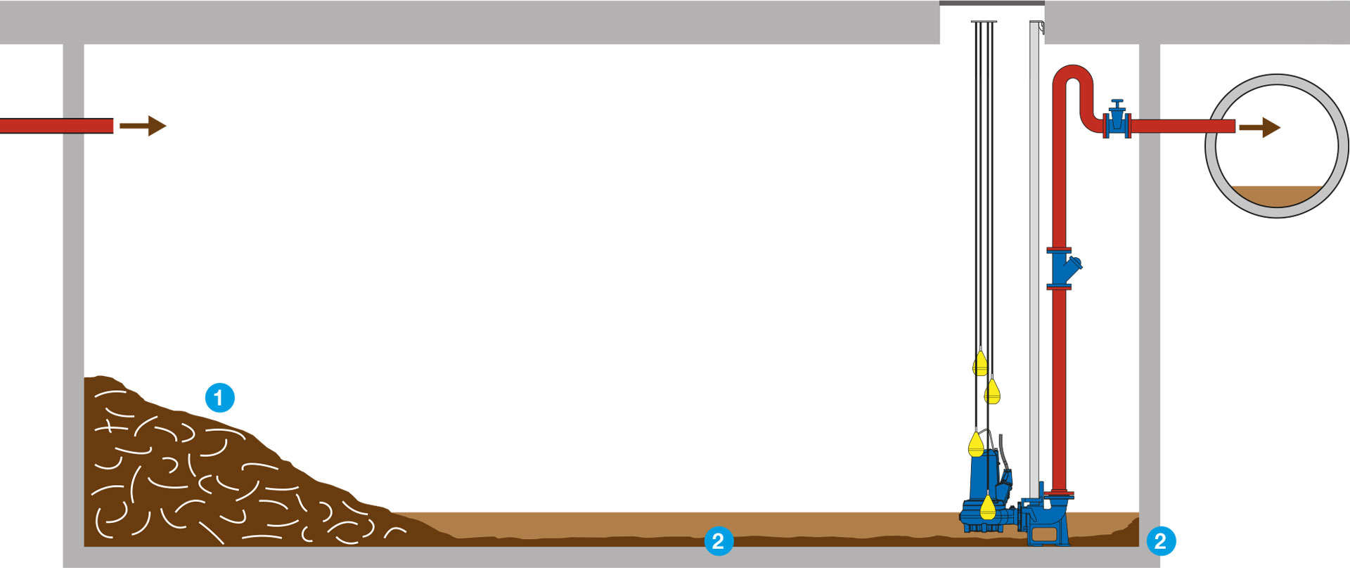
Figure 1. A basic concrete sump.
The inlet pipe is at the end of the sump furthest from the discharge pumps. Solids in the sewage, such as wet wipes and other textiles, as well as fat deposits, food waste and faecal matter quickly builds up underneath the inlet [1]. Over time it compacts to form a dense mass, a ‘mini-fatberg’, that will need to be broken down by jetting and then removed by tankering.
The floor of the sump is flat so the waste will flow slowly towards the discharge pumps. This lack of energy will allow suspended solids to settle and build up on the floor of the sump. Similarly, the perpendicular wall/floor junctions also create low energy zones leading to settlement of solids [2].
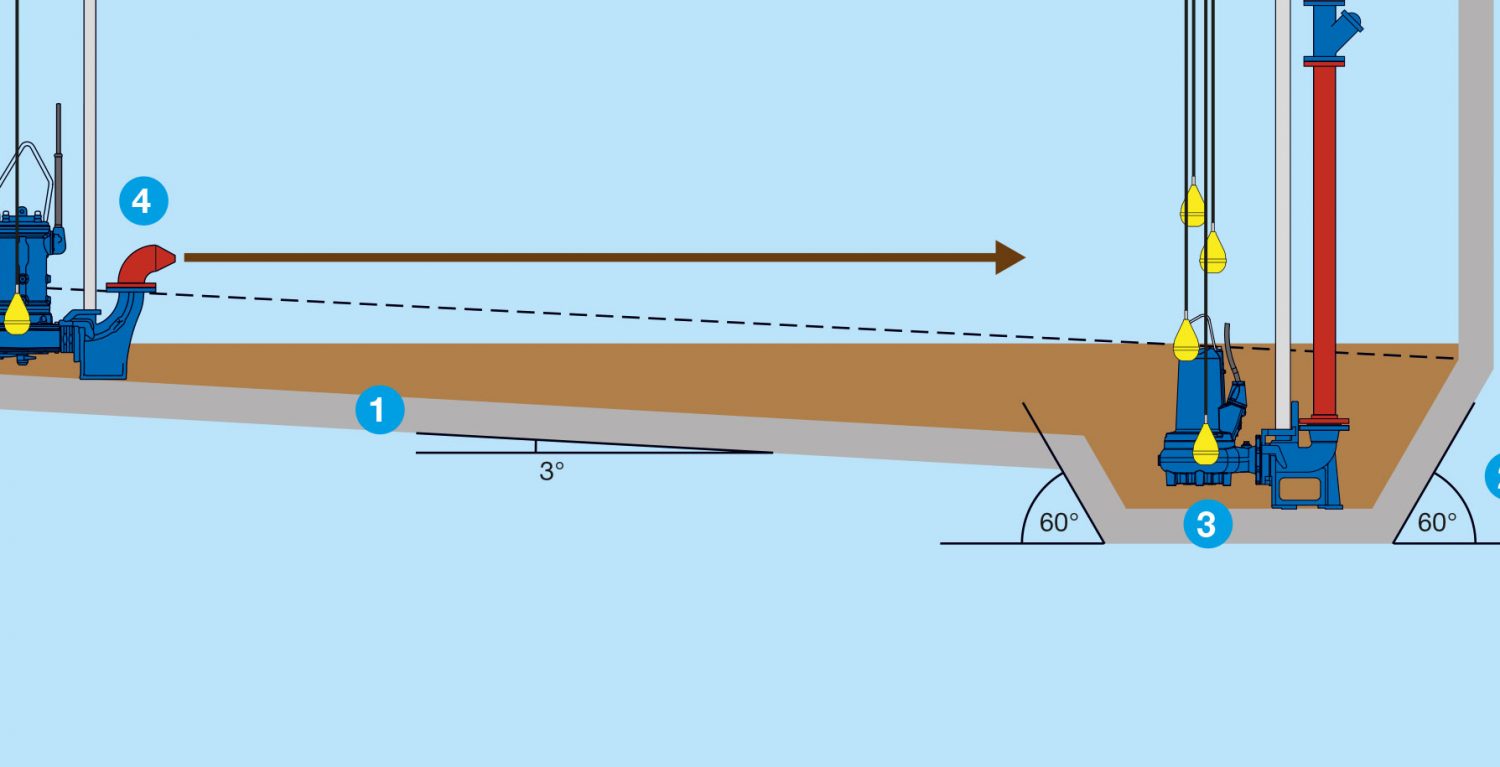
In contrast a few simple design features would greatly improve the sump’s performance, as shown below in Figure 2.
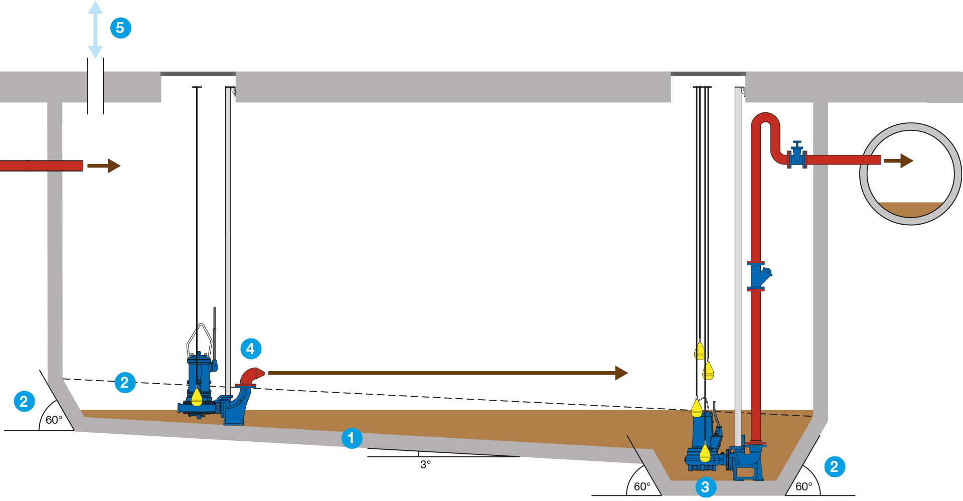
Figure 2. An improved concrete sump.
The floor slopes at a minimum of 3° to guide the waste to the discharge pumps and imparts energy so that solids stay in suspension [1].
Benching to all wall/floor junctions is included, with a minimum angle of 60°. This also guides the waste to the pumps and minimises the low energy zones where solids can settle [2].
The discharge pumps sit in a well in the bottom of the sump [3]. Waste concentrates below the pumps’ intakes so the sump remains as empty as possible.
With the inlet so far from the discharge pumps, a grinding mixer pump has been added. This will finely break down solids so that they will remain in suspension, before jetting the waste towards the discharge pumps. The mixer pump is fitted with a reducing funnel which acts just like a hosepipe nozzle, increasing the energy of the waste [4].
Lastly, any pump station chamber or sump must feature a vent pipe [5], which can be dedicated or connected to an SVP. This equalises pressure in the sump as it fills and empties, preventing odours and the accumulation of dangerous gases.
This quick guide is far from complete and is intended only as a broad guide to the key design features of a good concrete sump for foul water pumping stations. For more advice on designing sumps for pumping stations please contact our Technical Sales Team on 01442 211554.
If you have a project which requires a pumping station of any size or type, please contact our Sales Team on 01442 211554 for a free site survey and a no-obligation quotation.