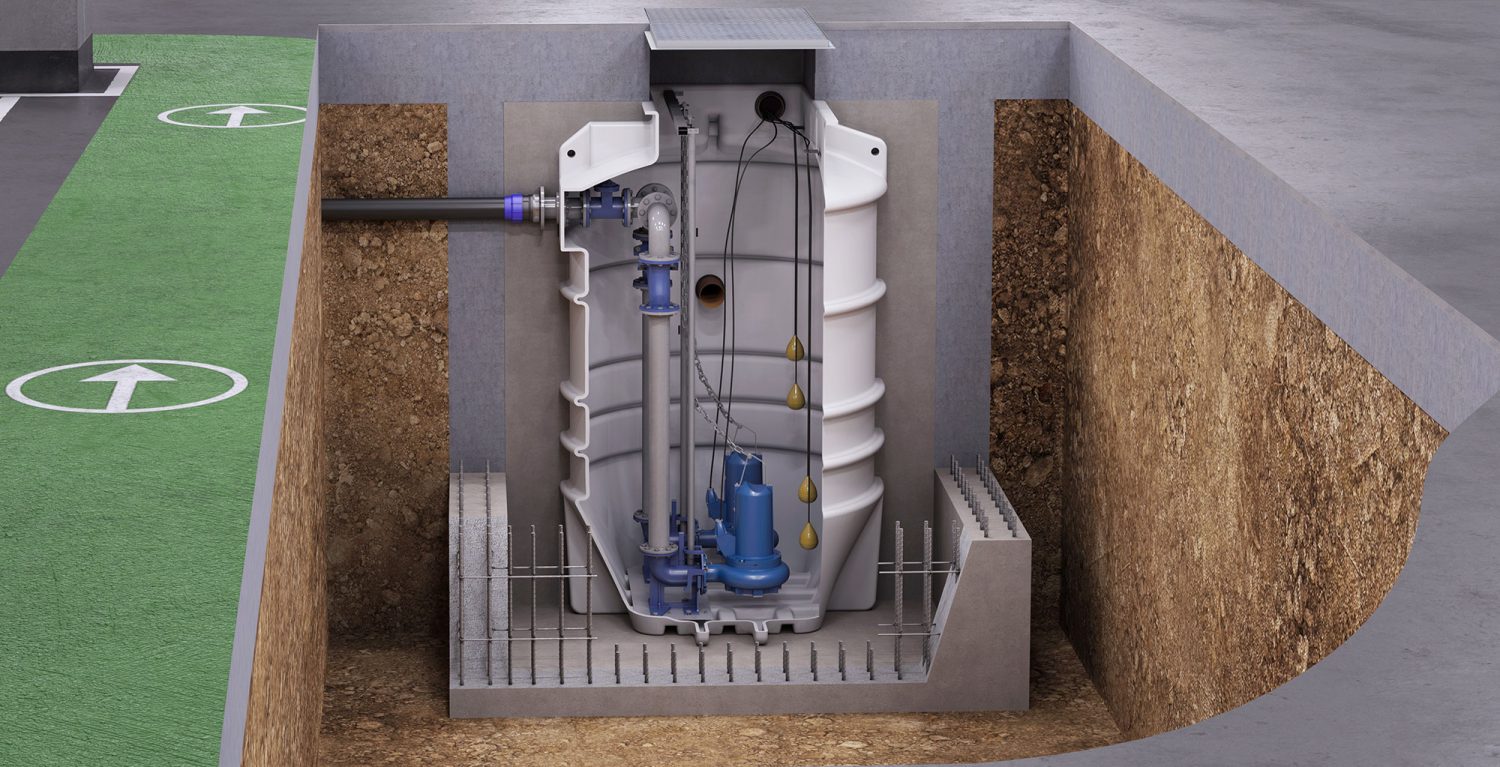
A packaged pumping station is used for pumping waste water to a higher level where gravity drainage is not possible.
In this article we’ll summarise the principal components.
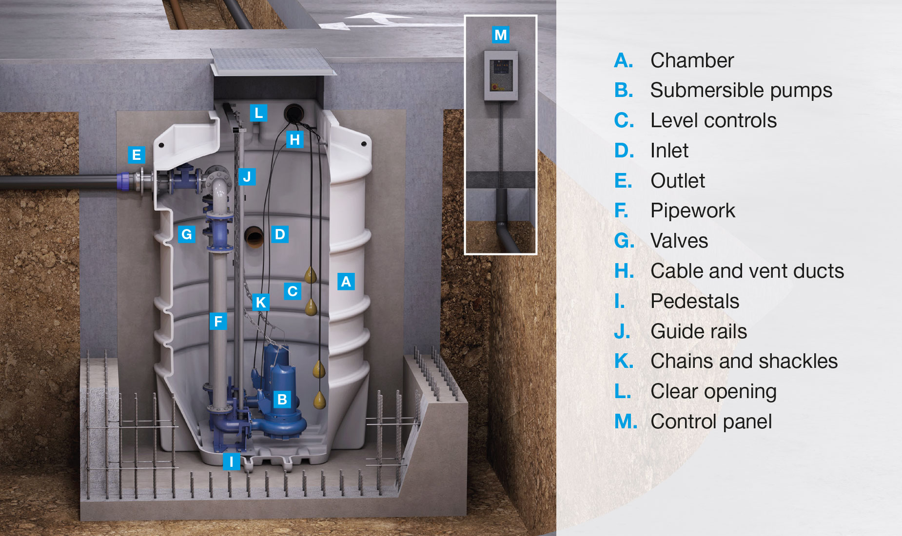
A. Chamber
The chamber encloses the equipment and provides storage for the waste water before it is pumped away. It is also a barrier between the waste water and the primary structure ensuring no contamination of the surround ground. It is usually fabricated from polyethylene or GRP (fibreglass).
When pump equipment is installed within a concrete or brick chamber, or pre-cast concrete rings, it’s called a sump instead.
B. Submersible pumps
The heart of the pumping station. These pump waste water from the bottom of the chamber, through the internal pipework to the final outfall. As their name suggests they’re designed to operate underwater. Pumping stations will usually have two pumps. Pump types and their selection are big topics which we’ll investigate in later articles.
C. Level controls
These are used to determine the height of the waste within the chamber so that the control panel can switch the pumps on and off and trigger a high-level alarm. They are many types of level controls which will be discussed in a later article.
D. Inlet
The inlet is the point where the waste enters the chamber. The invert level is the lowest point of the inlet point. When designing a pumping station, it’s the height of the invert not the whole chamber which typically determines capacity.
E. Outlet
The outlet or discharge is the point where the waste is pumped from the chamber into the external discharge pipework. The type of discharge is determined by the size of the pipework and the material used.
F. Internal pipework
The internal pipework including fittings like elbows and Tee Piece through which the waste water is pumped to the outlet. The arrangement of pipe and fittings is called a manifold. The type and diameter of pipe used depends on a number of factors. It can be fabricated from high pressure PVC, galvanised steel or ductile iron.
G. Valves
Non-return valves automatically prevent the waste water from flowing back into the chamber when the pumps stop. Gate valves can be closed manually to isolate the chamber from the external pipework to enable servicing or repairs to take place.
H. Cable and vent ducts
Cable ducts route float and power cables out of the chamber to the control panel. Vents connect to the atmosphere either directly or via a pre-existing soil vent pipe (SVP). They equalise pressure and prevent the build-up of noxious gases. Air admittance valves should not be fitted.
I. Pedestals
Pedestals are fixed to the base of the chamber and connect the pumps to the internal pipework. They allow the pumps to be easily disconnected and reconnected. A claw on the pump eases the pump into position. They also anchor the guide rails. Smaller pumping stations may not use pedestals, instead the pumps will be free-standing on the base of the chamber.
J. Guide rails
Guide rails are fixed to the pedestals at the base and via a horizontal strut to the top of the chamber. Submersible pumps can be very heavy. Guide rails allow them to be safely raised, lowered and position. Depending on the pedestal design there may be one or two guide rails per pump.
K. Chains and shackles
These are used to raise and lower the submersible pumps.
L. Clear opening
This is the hole at the top of the chamber that allows access. Maximum size is dictated by the size and design of the chamber and submersible pumps. It is covered by an access cover. Larger clear openings allow confined entry into the chamber using man-riding equipment.
M. Control panel
If the pumps are the heart of the pumping station then the control panel is the brain. It provides power to the pumps and uses the signals it receives from the level controls to switch the pumps on or off and trigger a high level alarm. Depending on the model it may include a number of features including battery backup, remote monitoring etc.
For further information or to discuss your project requirements please call 01442 211 554.
|
PREVIOUS ARTICLE |
NEXT ARTICLE |
|
| Simple tips for concrete sump design | Article index | When is a packaged pumping station the best choice? |
